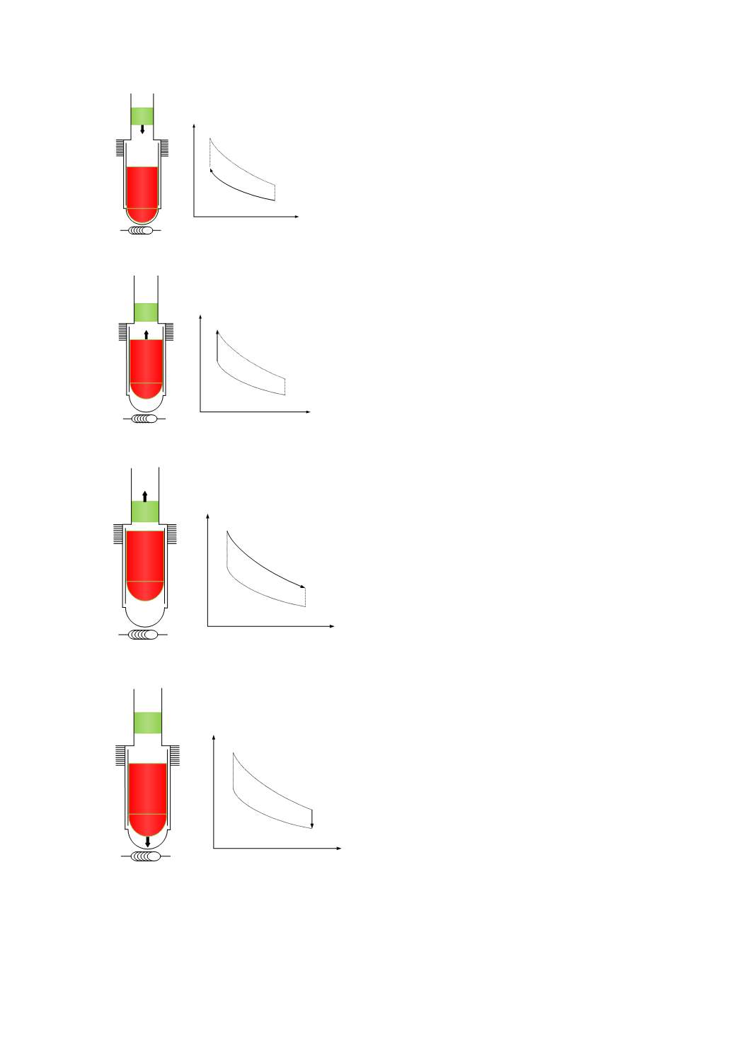
Fig. 2.Stirling Engine Cycle.
B.
Stirling Cycle
Stirling cycle as represented in Fig. 2 consists of four
processes as following:
Process 1–2: Isothermal compression.
At the beginning of the compression stoke the
displacer at BDC held there by its own weight then the
power piston is moved down, when it near BDC it
compress almost all gas into the displacer cylinder that
make pressure increase from 1 to 2 at constant
temperature. The work done on the working fluid
indicated by the area under process 1–2
Process 2–3: Constant-volume heating
The pressure acting on the displacer is high enough to
lift against its own weight, that transfer gas to expansion
space, rising the pressure still further so that eventually
the displacer is held at TDC. The displacer is pushing the
working fluid into the hot space, passing through a
regenerator which has stored heat, and already a certain
amount is being heated. Heat given up by the regenerator
raises the temperature and pressure of the working fluid
from 2 to 3 at constant volume, while the power piston
remains stationary at its BDC
Process 3–4: Isothermal expansion
After the displacer has pushed all the working fluid into
the hot space, with a corresponding increase in pressure to
the maximum, it is then kept at rest at its TDC. The
working fluid is in the hot space and is expanding to
pressure P4, while a constant temperature process 3–4 is
maintained at the hot space. The power piston is being
pushed from BDC to TDC by the increased pressure, and
is applying force to create mechanical energy. The work
done by the working fluid is indicated by the area under
process 3–4
Process 4–1: Constant-volume cooling
After the power piston has reached its TDC and has
supplied its energy to the load, it remains stationary and is
ready to travel back to BDC under its own weight and the
sucking action of the partial vacuum created by the falling
of pressure. The displacer is moving from TDC to BDC
and transfer working fluid to the cold space where the
pressure will fall and a partial vacuum is created, through
the regenerator, causing a fall in temperature and pressure
of the working fluid from 4 to 1 at constant volume. Heat
is transferred from the working fluid to the regenerator
[7].
C.
Schmidt’s Theory
Schmidt assumptions are typically used in the basic
analysis of the Stirling engine operation. The theory
provides the harmonic motion of the reciprocating
elements and retains the major assumptions of isothermal
compression and expansion because of the perfect
regenerator assume. It, thus, remains highly idealized, but
is certainly more realistic than the ideal Stirling cycle [8].
FREE-PISTON STIRLING ENGINE (FPSE)
A. FPSE Prototype
Free piston Stirling engine was invented by W. Beale.
The free piston Stirling engines (FPSEs) have no
kinematic mechanism coupling the reciprocating elements
Heater
Process 2-3
Constant-volume
heating
V
P
1
2
4
3
Heater
Process 3-4
Isothermal
expansion
V
P
1
2
4
3
Heater
Process 4-1
Constant-volume
cooling
V
P
1
2
4
3
Heater
Process 1-2
Isothermal
compression
V
P
1
2
4
3
2013 International Conference on Alternative Energy in Developing Countries and Emerging Economies
- 869 -


