ground) and that of slat surface (either right or left
surface). The luminance value of a patch of sky can be
computed using ASRC-CIE sky model [13]. The
luminance values of the right and left slat surfaces are
calculated from reflections of lights from the sun, the sky
and ground on the slat surfaces and the two panes of the
glazed window.
stands for the angle of incidence
between the line of sight and the normal to plan of the
wall segment.
and
are zenith angle and azimuth angle
of a point in a room, respectively.
The beam illuminance on segment
i
(
E
si
) due to the
non-slat reflected sunlight can be expressed as (2):
1
cos
(2)
cos
i
si
wo wi
b sw w n
j
j
j
E
F E A
A
In the equation,
E
sw
stands for the sunlight on the outer
glass pane.
wo
and
wi
are respectively visible
transmittances of the outer and inner glazed windows.
A
w
is the window area.
A
j
is the area of the sunlit segment
j
.
i
is the incident angle of the sunlight on the segment
i
,
and
n
is the total number of the segments in the room lit
by the sunlight. In the equation, a variable
F
b
represents
a fraction of the sunlit area to the total window area that
can be derived from geometrical position of the slats:
sin(
)
1
cos
b
b
b
W
F
S
(3)
Where
is the difference between solar azimuth angle
(
s
) and window azimuth angle (
w
),
W
b
is width of a
blind slat, and
W
b
is blind separation. Because this study
focused on the vertical slats where blinds tilted angle can
be positive or negative value, the absolute value of angle
were used in (3).
Actually, (2) is a balance of the flux of the sunlight
leaving from the inner glass pane of the slat window and
the flux falling on the sunlit surface segments in the
room. A segment is assumed to receive the sunlight if a
line drawn from the center point of the segment to the sun
is within the field of view from the point to the window
scene. The total direct illuminance from the window on
segment
i
(
E
i
) can be calculated as the sum of
E
di
and
E
si
.
To deal with the exchange of the light flux by multiple
reflections between the small segments of the interior
surfaces, form factors are calculated for the whole
segments. The form factors are then used in radiosity
method in determining the internally reflected
components of the daylight and the total daylight
illuminance on the segments. In the final step, the
configuration factors between points on the work plane
and the segments are determined and used to calculate the
workplane illuminance.
C. Experimental Results
Results from the experiments were used to illustrate
characteristics of the interior daylight from the slat
window in the tropics. The results were also used to
validate the algorithms described in Section 3.
An experiment of the window with slat angle of 30
was conducted on 4
th
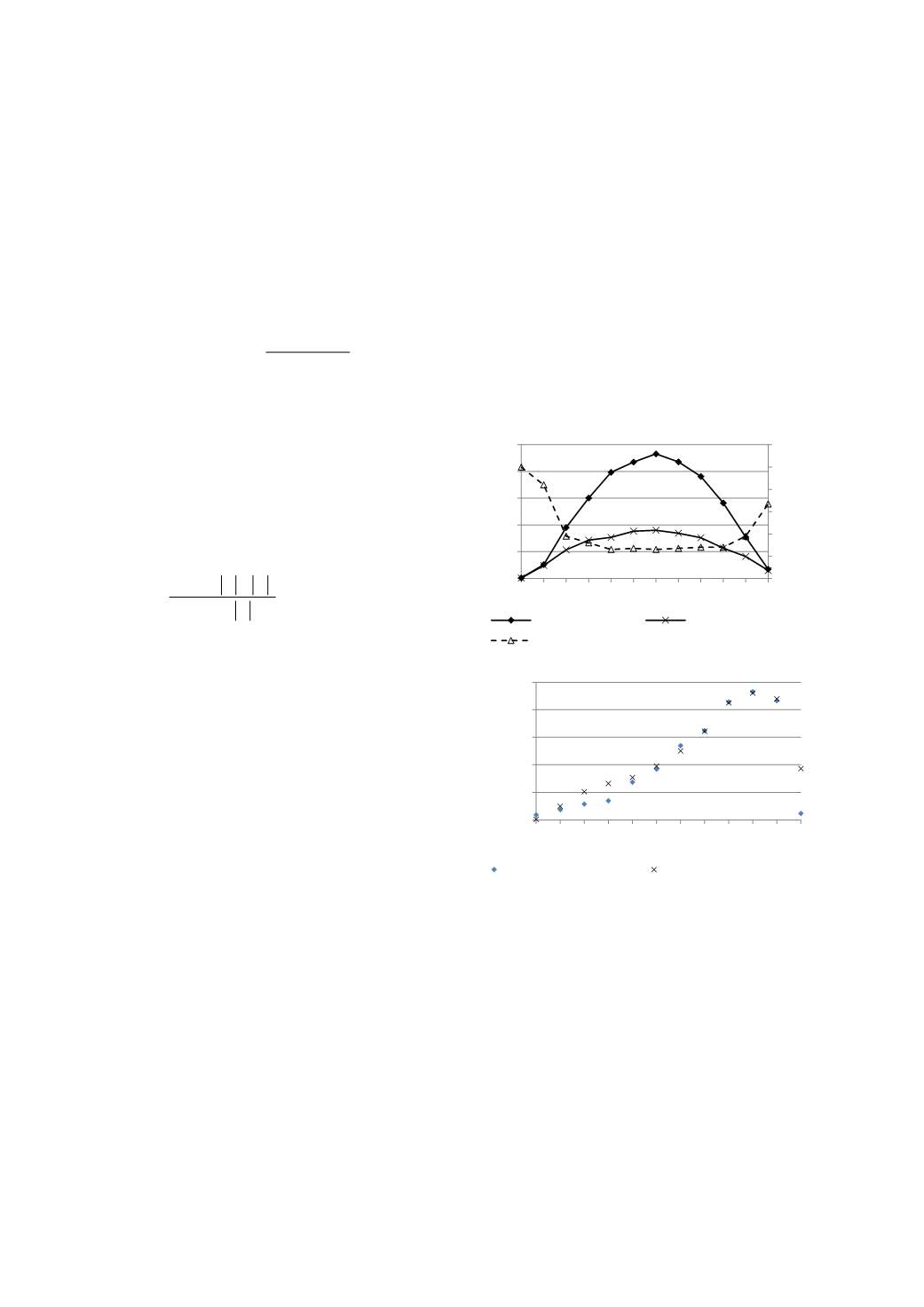
February 2013. Fig. 3(a) shows a
plot of the global and the diffuse horizontal illuminances
measured on the date of experiment. Variation of an
insolation index namely sky ratio is also exhibited in the
plot. It can be observed that the values of sky ratio fell
between 0.3 and 0.5 excluding those in the early morning
and in the late afternoon. The sky was rather clear on the
experimental day.
Fig. 3(b) exhibits the measured workplane
illuminances in the middle of the room when the blinds
were fixed at 30 degree. It is observed that the
illuminance values of the illuminance were still beyond
500 lux for most of the afternoon (13:00-17:00). The plot
also shows a good agreement between the measured
illuminance values and the corresponding values obtained
from the calculation.
(a) Exterior daylight and sky condition
(b) Interior illuminance
Fig. 3. Experimental results of the window with a slat angle 30
on
4
th
February 2013.
D. Simulation-Based Analysis
The validated algorithm was used to simulate the
daylight from the slat window for a whole year. A
complete one-year hourly record of the daylight and solar
radiation measured in Thailand was used for the
simulation. In the simulation, a model room was set
similar to the test room but its length was extended to 15
m. allowing daylight to penetrate deep into the interior
without the limit of room depth. Values of the interior
surface reflectance were defined to 0.7 for ceiling, 0.5 for
walls and 0.3 for floor identical to those in the IES
Lumen method for daylight calculation [15]. No
modification was made for the blind properties.
0
0.2
0.4
0.6
0.8
1
1.2
0
20
40
60
80
100
7 8 9 10 11 12 13 14 15 16 17 18
Illuminance (klux)
Time (hr)
Global Illuminance
Diffuse Illumiance
Sky Ratio
0
200
400
600
800
1000
7 8 9 10 11 12 13 14 15 16 17 18
Illuminance (lux)
Time (hr)
measured illuminance-30deg calculated illuminance-30deg
2013 International Conference on Alternative Energy in Developing Countries and Emerging Economies
- 586 -


