back side of the absorber plate and an air cooled
aluminum fin heat sink with a brushless fan. Moreover, in
order to minimize the thermal contact resistance, a layer
of heat conductive silicone grease was applied to all the
contact surfaces. A schematic diagram of the TE
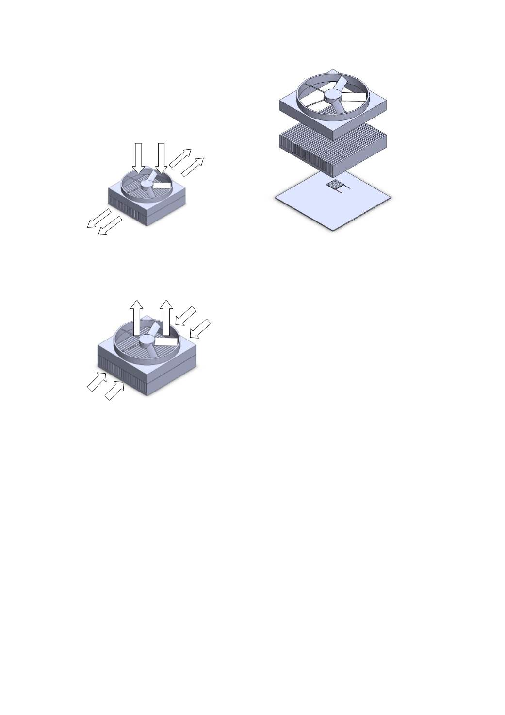
generator system is shown in Fig. 3.
(a) Air Pushing
(b) Air pulling
Fig. 3. A schematic diagram of the TE generator system.
Fig. 1 also shows the TE generator system as placed
in the focal area of the parabolic concentrator. The solar
parabolic concentrator coupled to the TE generator was
mounted on a one axis tracking base. Tracking of the sun
was done manually.
In this study, the effects of fan orientation, namely, air
either being pushed or pulled through the fin heat sink
(see Fig. 4), and the air flow rate on the performance of
the TE generator were assessed.
Fig. 4. Fan orientation.
The TE generator system was instrumented with T-
type (accuracy
0.5
C) thermocouples at the hot and cold
sides of the TE module and heat sink. The thermocouple
that measured ambient temperature was kept in a shelter
to protect the sensor from direct sunlight. A normal-
incidence pyrheliometer (Eppley accuracy
10 W/m
2
)
was used to measure the direct solar radiation. The air
flow rate was calculated from the air velocity, measured
by a hot wire anemometer (Testo model 445, accuracy
0.03 m/s). The output current and voltage were
measured with a multi-meter (Fluke model 189, accuracy
VDC
0.025%, A
0.5%). Experimentation started at 9
a.m. and ended at 4 p.m.
C
ALCULATION
M
ETHODS
The incoming solar radiation incident (S) on the
absorber plate is
b
IaρcAS
(1)
Where A is the area of the solar collector (or
reflector), ρ
a
is the reflectance of the reflective material
(0.85 for aluminum foil) and I
b
is the beam solar radiation
The total heat dissipated by the cooling air (Q
t
), which
can be obtained by using Eq. (2) as
amb
T acoTpaCam tQ
(2)
where C
pa
is the specific heat at the average air
temperature, m
a
is the air mass flow rate, T
aco
and T
amb
are
the air temperature at the outlet of heat sink and ambient
temperature, respectively.
The electrical output of the TE solar collector (P)
is
calculated from the measured data as follows:
VI P
(3)
where I is the maximum current of the TE modules at a
matched load. V is the maximum voltage of the TE
modules at a matched load.
Fan
Heat sink
Air Inlet
Air outlet
Air outlet
Air Inlet
Fan
Heat sink
Thermoelectric module
Absorber plate
2013 International Conference on Alternative Energy in Developing Countries and Emerging Economies
- 727 -


