2011 International Conference on Alternative Energy in Developing Countries and Emerging Economies
- 107 -
VIBRATING
FEEDER
BIOMASS
HOPPER
ORIFICE
PLATE
WATER IN
WATEROUT
SAND
LOADING
PORT
SAND
WITHDRAWAL
PORT
SCREW CONVEYOR -
I
SCREW
CONVEYOR - II
DCMOTOR
DCMOTOR
(BEDPRESSURE
DROP)
CYCLONE
SEPARATOR
ASH
BOX
REACTOR
TRANSPORT
DISENGAGEMENT
SECTION
AIRFLOW
CONTROL
VALVE
T10
ORIFICE
PLATE
T1
T2
T3
T9
T4
T6
T7
T8
T5
P
TO
MANOMETER
TO
MANOMETER
TO
MANOMETER
BLOWER
GAS
BURNER
T : Thermocouple
P : Manometer
P
P
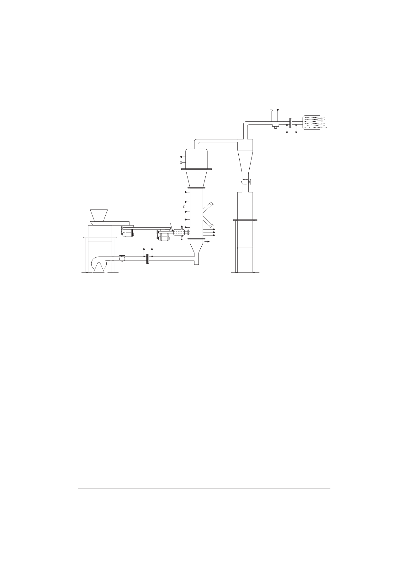
Fig. 1. Schematic diagram of fluidized bed gasifier experimental unit.
flanges of the fluidizing column and that of the calming
section. The atmospheric air was used as the fluidizing
and gasifying agent for the biomass gasification process.
A blower (Make: Ralliwolf) supplied air continuously at
a maximum rate of 1.5 m
3
/min. The biomass feeding
system comprised of (i) an electrically operated vibrating
feeder (Make: Saideep Electricals, Bombay), and (ii) two
screw conveyors. The hopper of size 300 mm
u
300 mm
u
450 mm was mounted on the vibrating feeder. The feed
biomass material was discharged from a rectangular slit
provided at the bottom of this hopper due to vibrations of
the vibrating feeder. Two screw conveyors, one 600 mm
long and the other 400 mm long, of the same auger
dimensions were used in further transporting the biomass
to the reactor. A high efficiency cyclone separator was
attached to the exit pipe of gas from the fluidized bed
reactor to capture the solid particles (dust, ash, char)
entrained in the gas stream. The cyclone outlet was
connected to a horizontal pipe, which incorporated a
sampling port and an orifice meter at horizontal
recommended distances. The gas outlet pipe had a small
pilot burner using liquefied petroleum gas (LPG), which
was used to trigger flaring of the gas from the cyclone gas
exit pipe.
B. Gasification Runs
Each experimental run comprised the gasifier
operation and the sampling & analysis of the gas. The
gasifier operation included: start up of the gasifier, steady
state operation, and shut down. The gas sampling and
analysis included tar sampling and analysis, particulate
matter sampling alongwith the compositional analysis of
the gas. The gasification experiments were conducted to
evaluate the performance of the fluidized bed biomass
gasifier at different equivalence ratios (0.20 to 0.40) and
fluidization velocities (0.53 to 0.73 m s
-1
) with village
rice husk (VRH) and sawdust (SD) as the two biomass
feed materials. The amount of actual air needed for the
complete combustion of the biomass was first calculated.
The stoichiometric air for one kg of village rice husk was
found to be 4.85 kg where as for the sawdust it was found
to be 5.2 kg. The desired value of equivalence ratio then
was obtained by suitably adjusting the feed flow and
airflow. Gasification experiments were performed, for
each of the feed material, at four fluidizing air velocities
of 0.53, 0.59, 0.68 and 0.73 m s
-1
. Five equivalence ratios
of 0.20, 0.25, 0.30, 0.35 and 0.40 were adopted for each
fluidizing air velocity. Experimental observations were
noted under steady-state condition.
C. Start-Up of the Gasifier
A predetermined quantity of sand of suitable size as
the carrier solid was loaded into the reactor through the
loading port. The blower was switched on and the airflow
rate control valve was opened slowly to the maximum.
After fluidizing the sand for 2-3 minutes the airflow was
stopped. The biomass-feeding unit was started and a little
amount of biomass was fed. Two side peepholes (12 mm


