2011 International Conference on Alternative Energy in Developing Countries and Emerging Economies
- 128 -
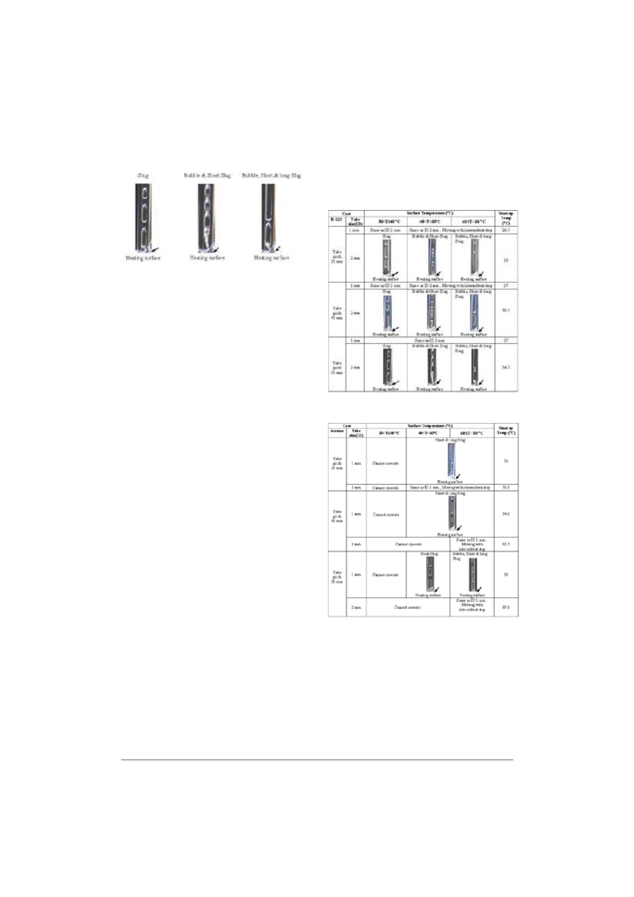
30<T
d
40
q
C 40<T<60
q
C 60
d
T<80
q
C
Fig. 5. Flow patterns inside CLOHP at various surface temperatures.
B. Effect of capillary tube diameter
In this experiment, the capillary tube diameters were 1
mm and 2 mm. The results were shown in Table 2. The
experimental results showed that the boiling inside the
capillary tube in case of 2 mm diameter was better than
that of 1 mm. Since, the friction force between bubble and
capillary tube surface played an important role on the
moving of bubble and the 1 mm tube gave higher friction
than that of the 2mm one. Therefore, the movement of
bubble in case of the bigger diameter was better than that
of the smaller one.
C. Effect of working fluid
In this work, R123, acetone and methanol were
selected as working fluids in the capillary tube. From the
results shown in Table 2, it was found that the boiling of
the working fluid depended of the boiling point. At normal
pressure, the boiling points of R123, acetone and methanol
are 27.8
q
C, 56
q
C and 64.7
q
C respectively. Therefore, the
results showed that R123, due to its low boiling point,
could operate suitably at lower temperature than acetone
and methanol while acetone and methanol could operate
when the surface temperature was over 40 and 60
o
C,
respectively.
D. Effect of main tube pitch
In this work, the tube pitch was varied which were 30
mm, 40 mm and 50 mm. In case of R123 shown in Table
2, it was found that the boiling performance observed from
the flow pattern was directly proportional to the tube pitch.
Since the capillary tube acted as an extended surface so
higher tube pitch meant that higher heat transfer length of
the oscillating heat pipe was obtained which resulted in
higher heat transfer rate.
This result agreed well with our previous work [9]
that the higher tube pitch brings to get the increasing of
heat transfer performance of wire-on-tube heat exchanger
having oscillating heat pipe fin.
TABLE II
F
LOW PATTERNS INSIDE CLOHP
(A) C
ASE OF
R123
(B) C
ASE OF ACETONE


