2011 International Conference on Alternative Energy in Developing Countries and Emerging Economies
- 231 -
Prime mover
Induction
generator
(SEIG)
Cs
Cs
Cp
Consumer
Load
Voltage
sensor
ATmega 328
Arduino
Duemilanove
ADC
GPIO
Opto
Dump load
Power
MOSFET
Bridge retifier
IGC
ATmega 328 8-bit AVR microcontroller which provides
a better performance, with increased operational
flexibility. Based on this design and implementation,
prototypes of IGC are developed and tests are performed
on them with the SEIG under steady-state and transient
conditions.
II. M
ATERIALS AND METHODS
The IGC action of the switch is carried out by a micro-
controller which generates the PWM pulses based on the
errors in the voltages being compared. When the chopper
switch is switched on, the current flows through the
dump load and consumes the difference in power which
results in a constant load on the SEIG and constant
voltage and frequency at the load. That is,
D L G
P P P
(1)
where
G
P
is the generated power of the generator (W),
L
P
is the consumer load power (W), and
D
P
is the dump
load power (W).
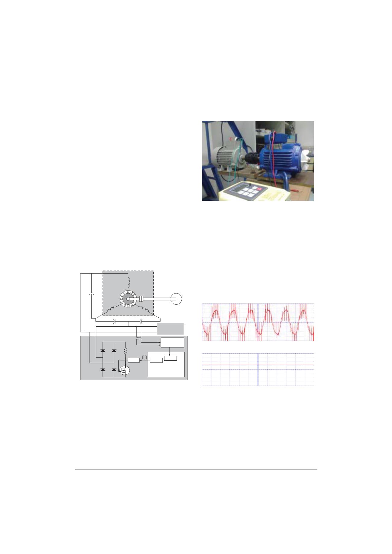
A prototype microcontroller-based SEIG-IGC for pico-
hydro systems has been developed and tested in a
laboratory under various operating conditions. A
schematic diagram of the prototype microcontroller-
based SEIG-IGC system is shown in Fig.1.
Fig. 1. Schematic diagram of a three-phase SEIG with an ICG feeding
single-phase loads.
A three-phase 0.37 kW, 230/400 V, 2.1/1.2 A, 50Hz, 6
pole, 920 rpm star-connected squirrel cage induction
machine is used as a single-phase self-excited induction
generator. To generate 100W at 230V and rated speed, an
8 μF and 8 μF capacitor of 370 V is connected as CP and
CS at the SEIG terminals. The SEIG is driven by a three-
phase 0.75 kW, 230/400 V, 3.5/2.0 A, 50Hz, 4 pole, 1380
rpm induction machine used as a prime mover. A resis-
tive load of 100 W is connected as dump load. A resistive
load, which can be varied from 0 to 100 W in 25 W
steps, is used as the consumer load, as shown in Fig. 2.
Fig. 2. The SEIG and prime mover for this study
The GBPC5008 800V/50A diode bridge rectifier
converts the SEIG ac terminal voltage to dc. An
IRFP460PbF 20A/500V power MOSFET N-Channel
power MOSFET is used as a chopper switch. The core of
this IGC is ATmega 328 Dev board, which implements
control algorithms. It is Arduino Duemilanove-
compatible, with a microcontroller board based on the
ATmega 328 8-bit AVR microcontroller. The SEIG
terminal voltage is stepped down and rectified to a dc
voltage proportional to the terminal voltage, as shown in
Fig. 3. This voltage is given to 10 bit on the chip ADC of
the ATmega 328 microcontroller, which converts the
input signal to a digital value. It reads the input with a
sample rate of 10 milliseconds.
(a)
(b)
Fig. 3. (a) SEIG terminal voltage and (b) output of feedback signal
circuit.
The proportional-integral-derivative control algorithm
(PID) was selected as the controller, since it is probably
the most extensively used method in industrial process
control applications [6]. A PID controller is a generic
loop feedback mechanism. It measures a process variable


